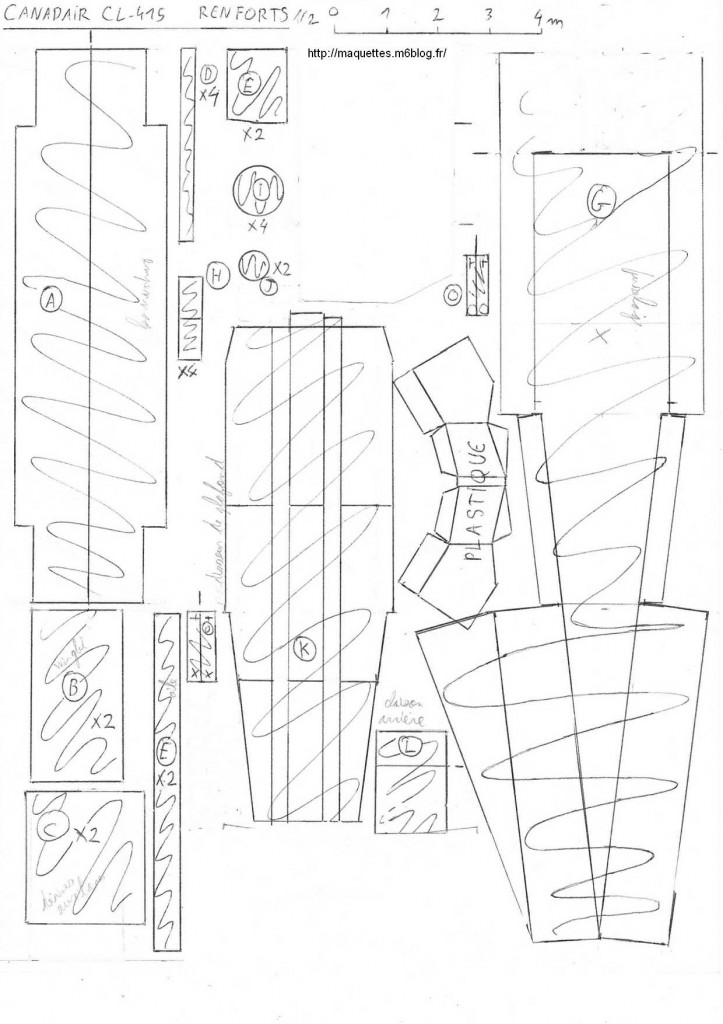
Renfort de l'aile par baguette en bois de 10mm x 10mm sur toute la largeur de l'aile soit environ 42 cm ! Le carton fin n'est pas envisageable, même plié et un carton ondulé ne sera pas rigide dans toutes les directions !
Reinforce the wing with wood stick of 10mm x 10mm on all the wing width (approximately 42 cm) ! You cannpt use thin cardboard, not even folded and corrugated cardboard will not be stiff in all the directions !
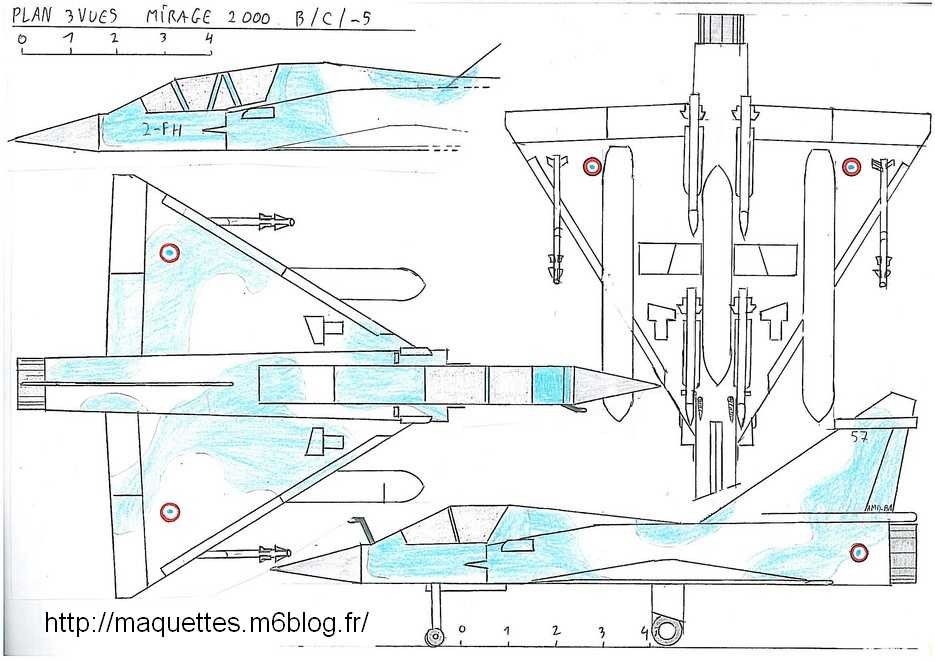
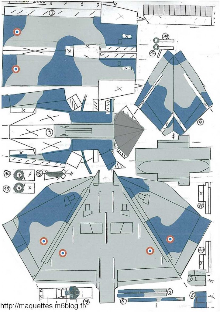
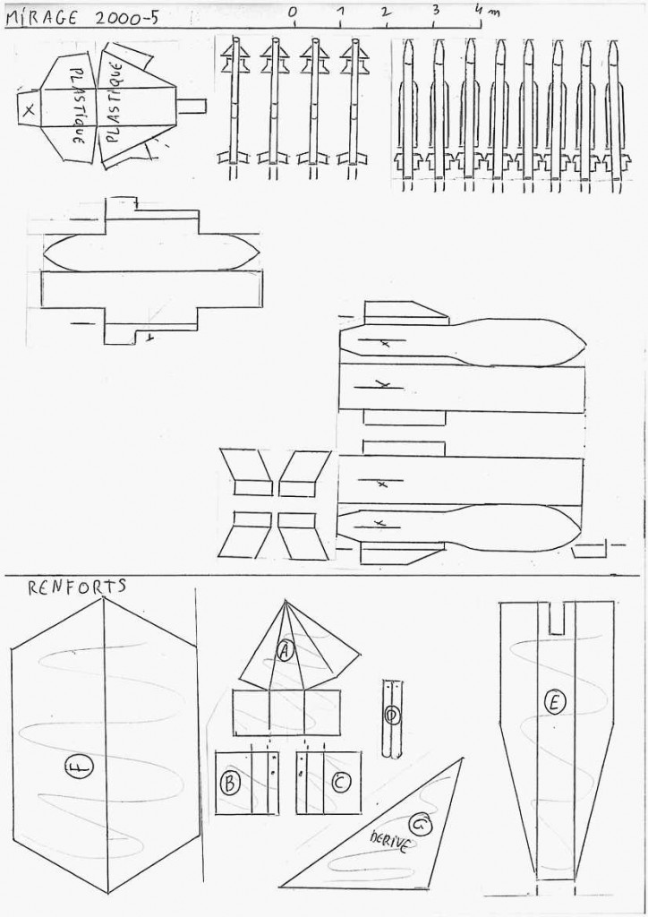
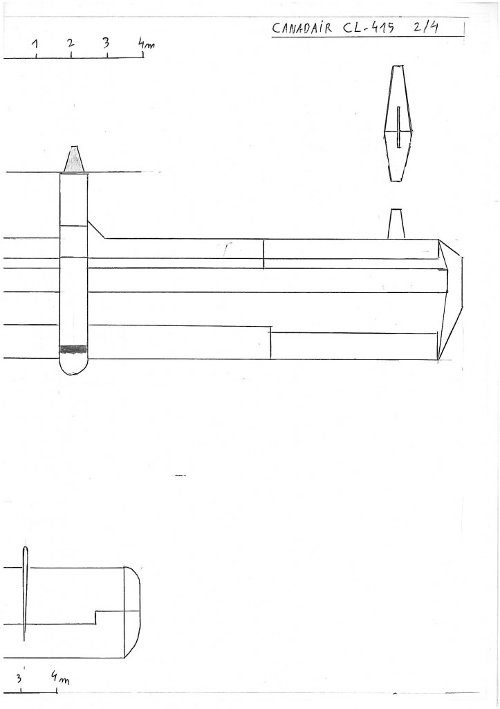
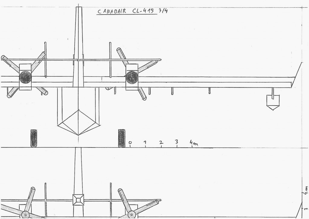
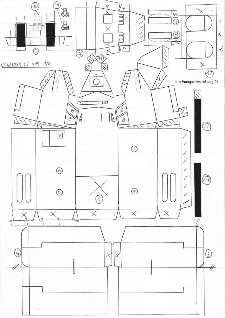
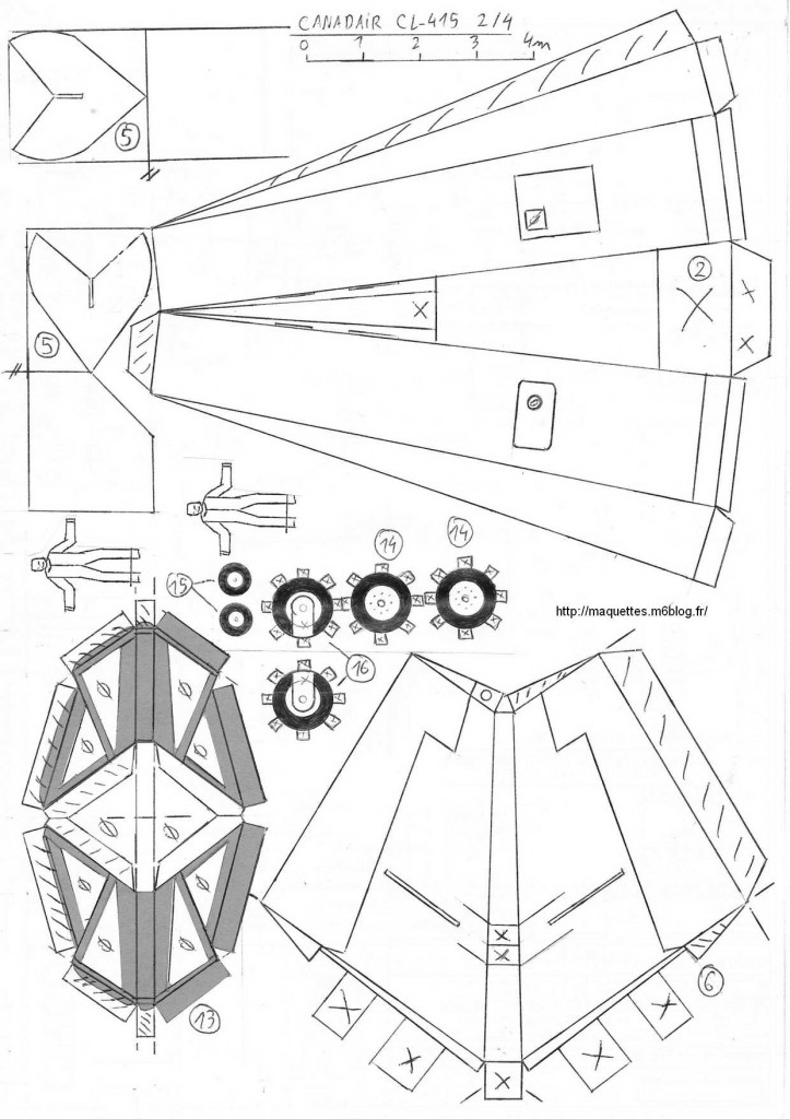
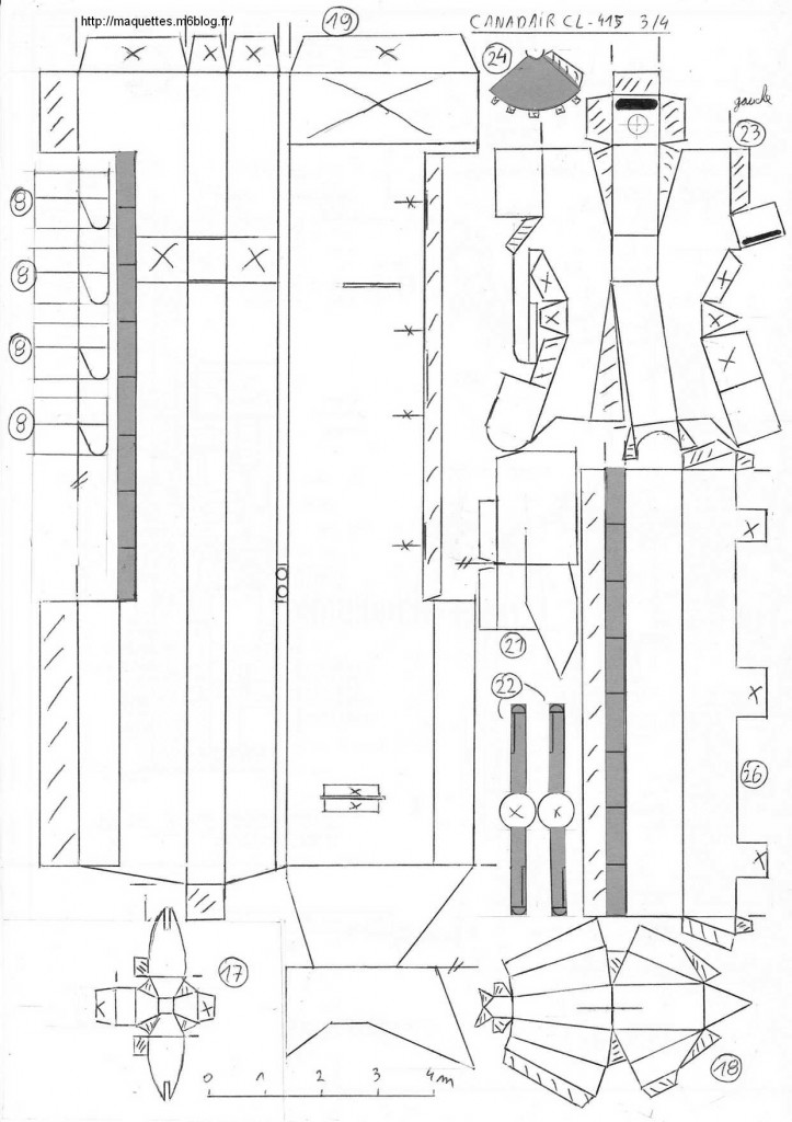
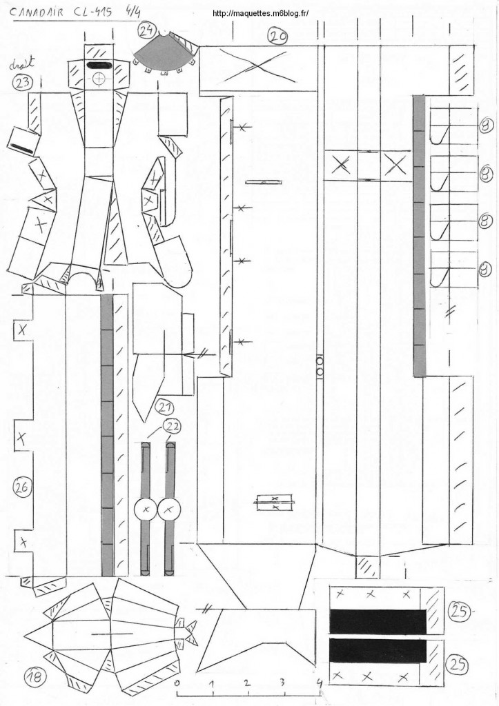
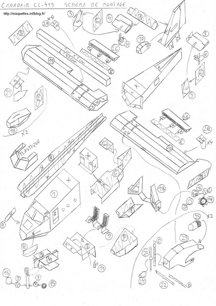
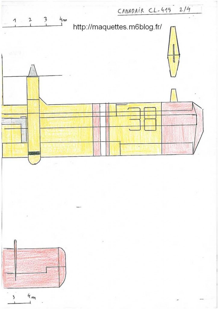
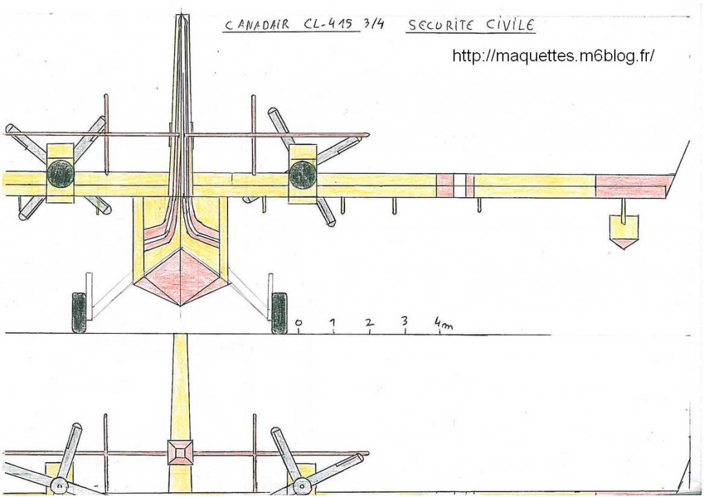
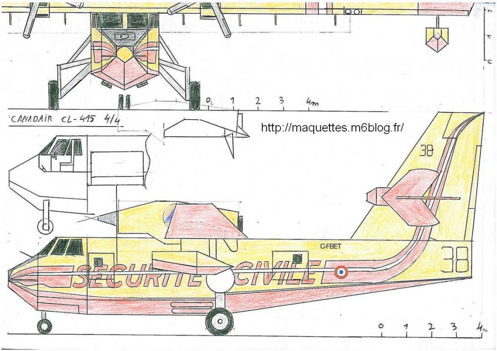
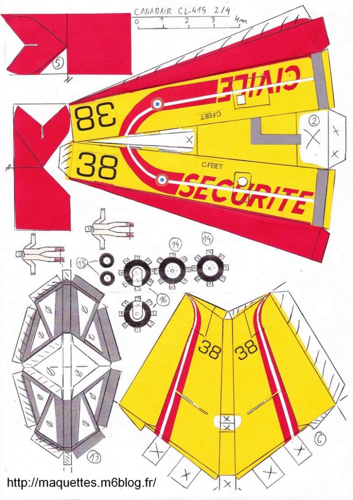
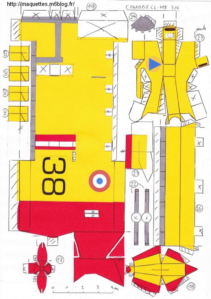
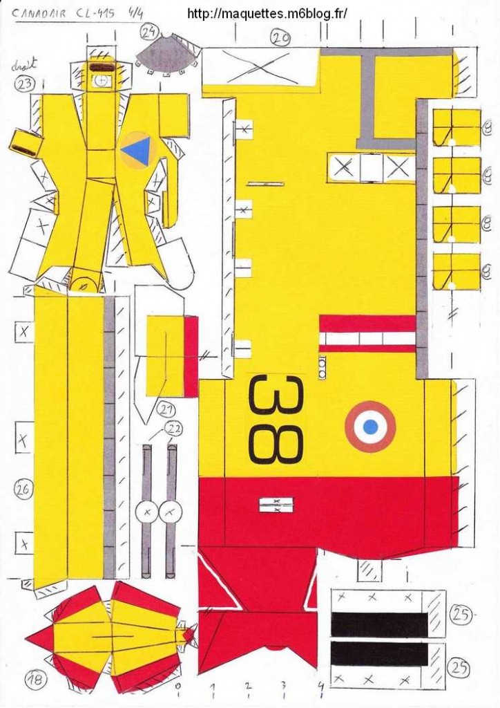
Pour télécharger le plan 3 vues en noir et blanc , des pièces noir et blanc et le schéma
de montage du Candair Cl-415 au 1/66 en pdf /
To download the 3 sights plan in black and white, black and white parts and installation diagram of Cl-415 Canadair in 1/66 pdf,
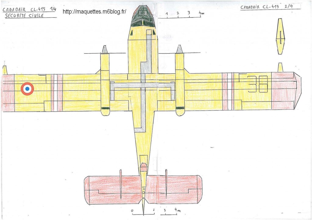
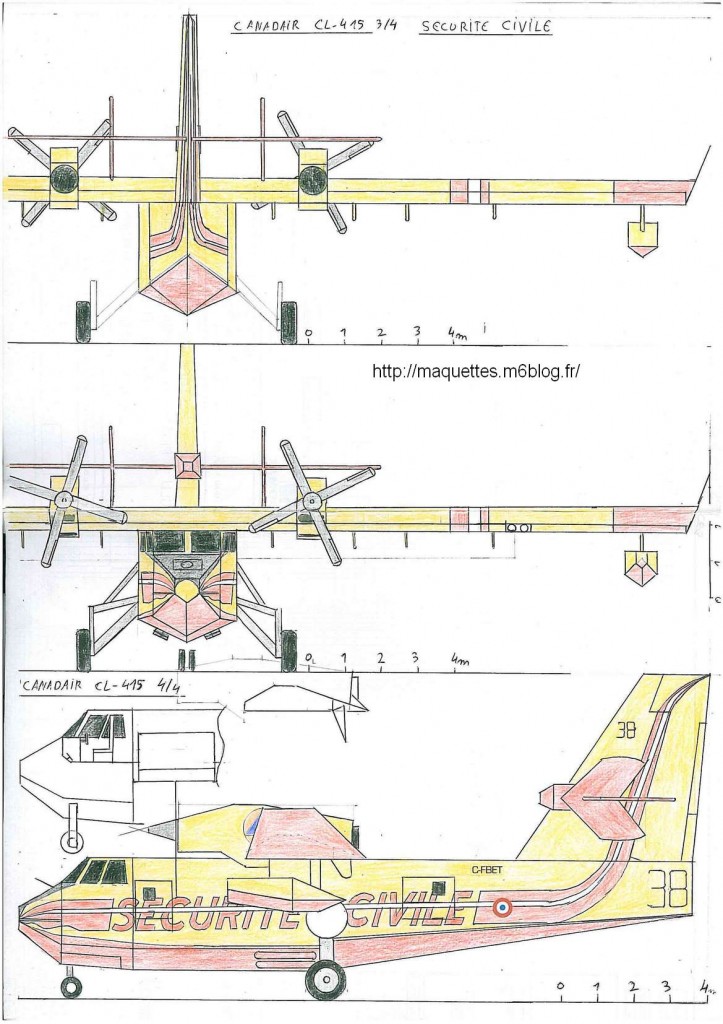
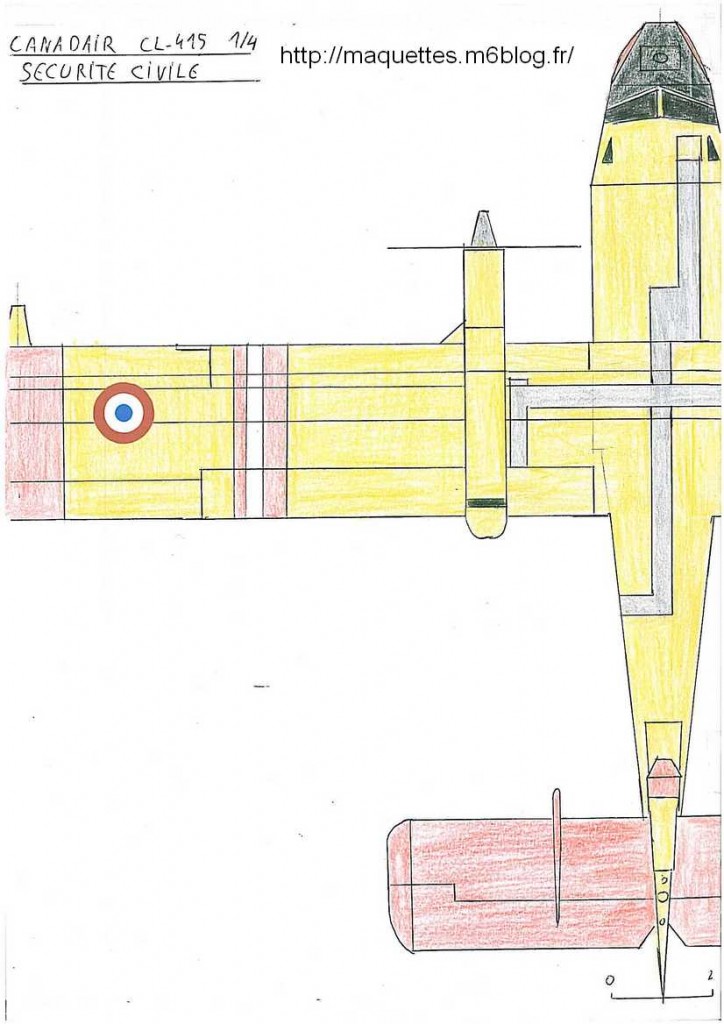
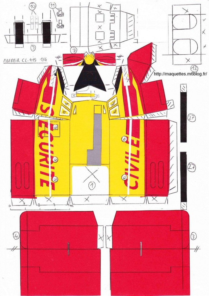
CLIQUER ICIPour télécharger le plan 3 vues et de pièces en couleur du Canadair CL-415 de la sécurité civile française au 1/66 en pdf / To download the 3 sights plan in color, and color parts of Cl-415 Canadair of french civil safety in 1/66 pdf, CLIQUER ICI
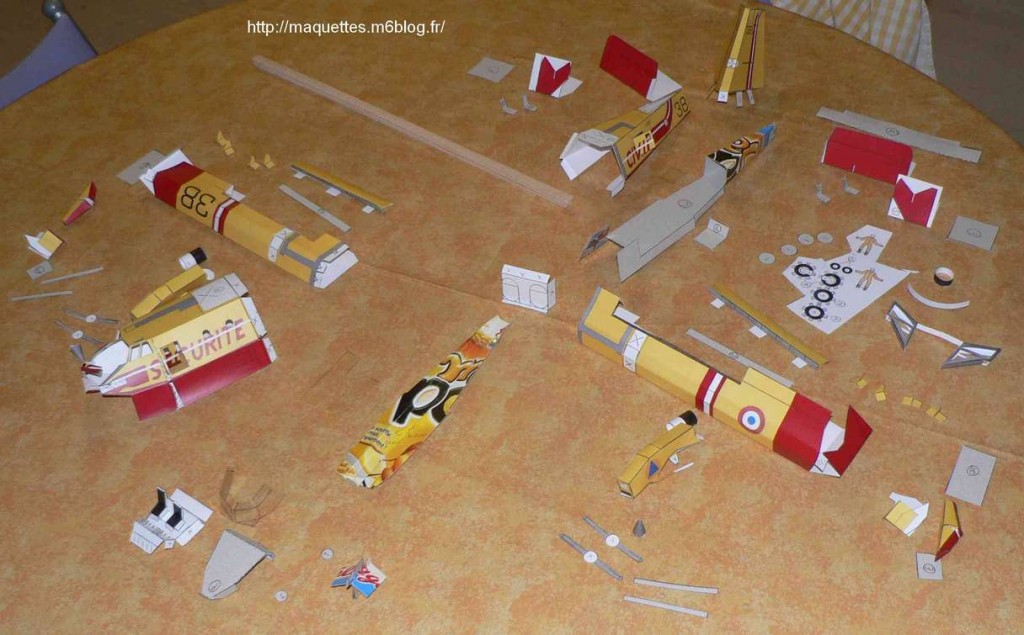
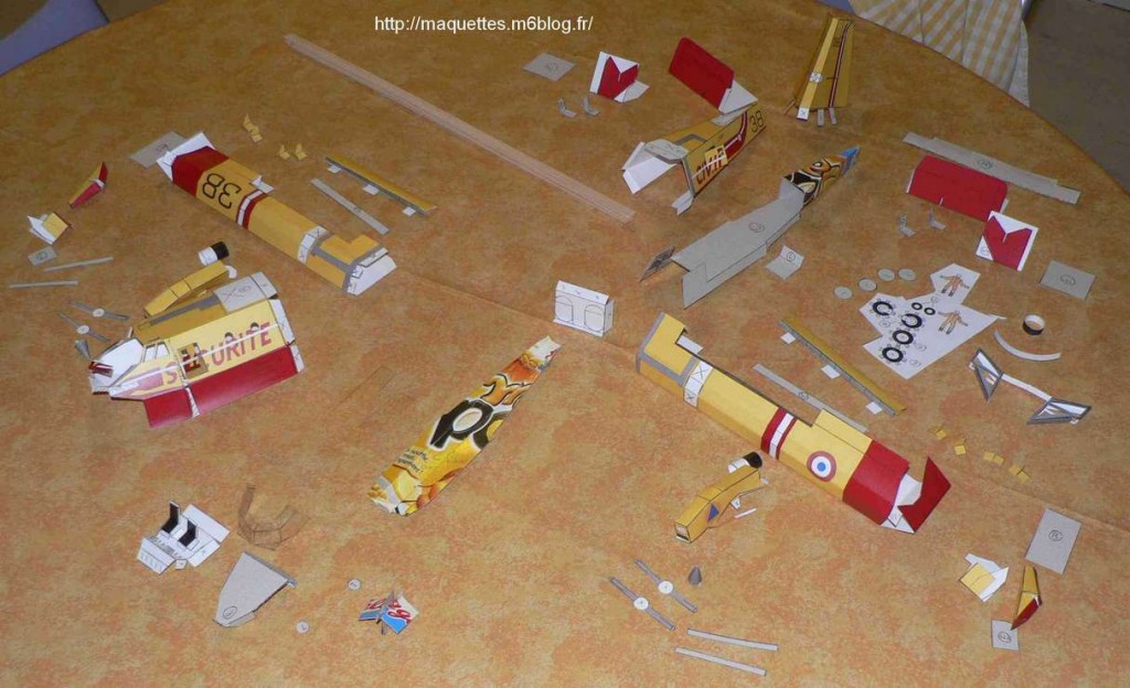
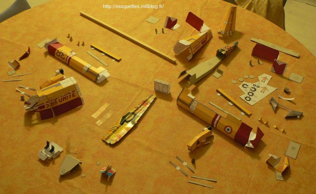
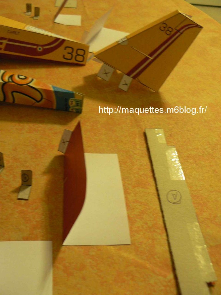
photos des pièces avant assemblage / parts pictures before assembly
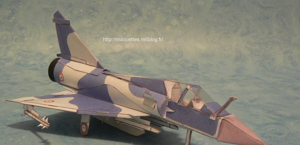
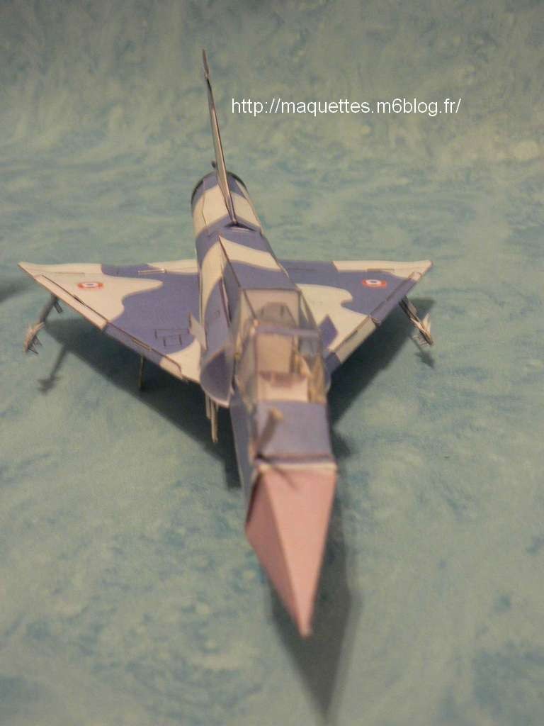
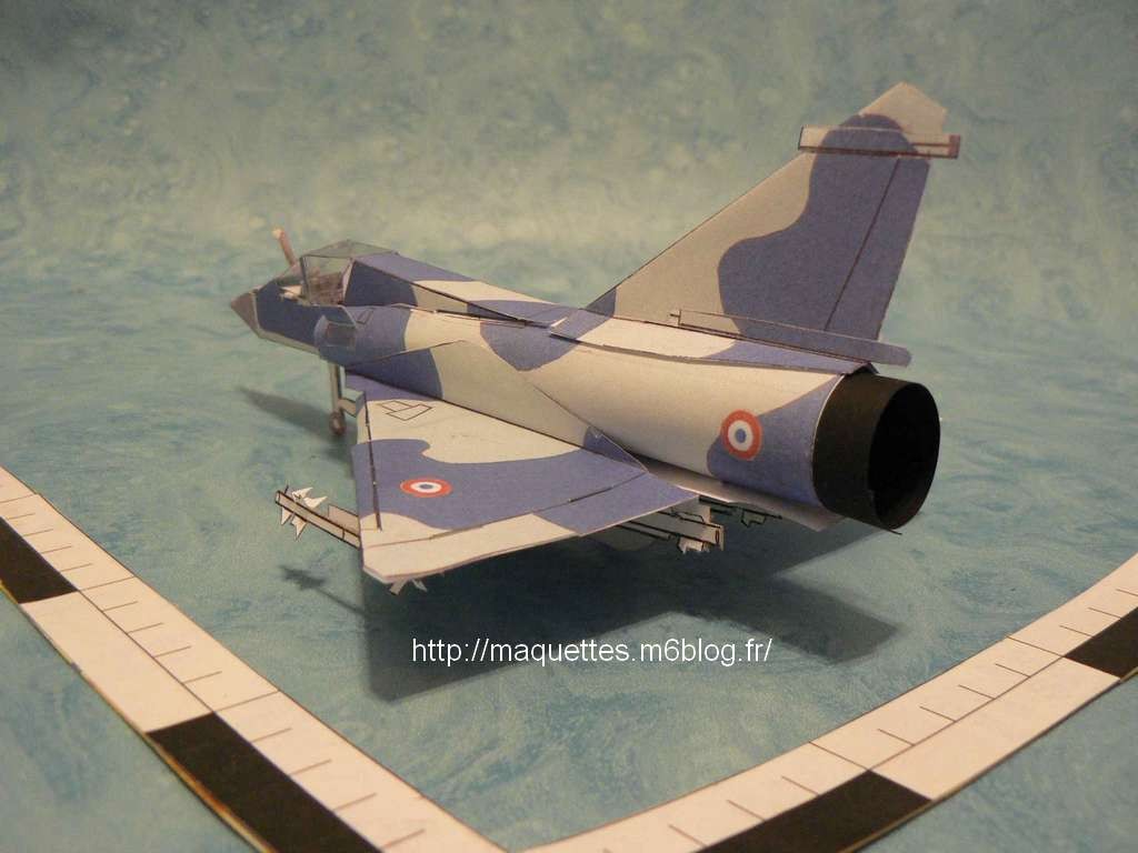
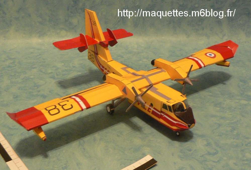
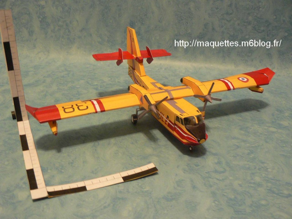
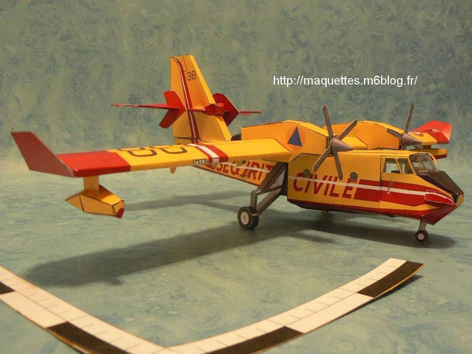
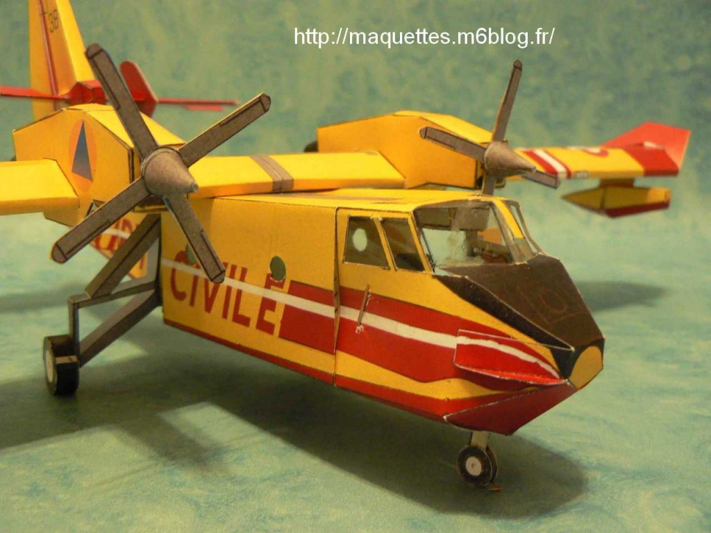
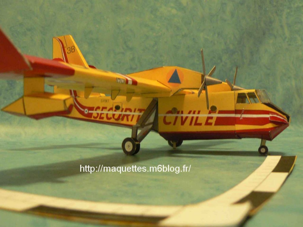
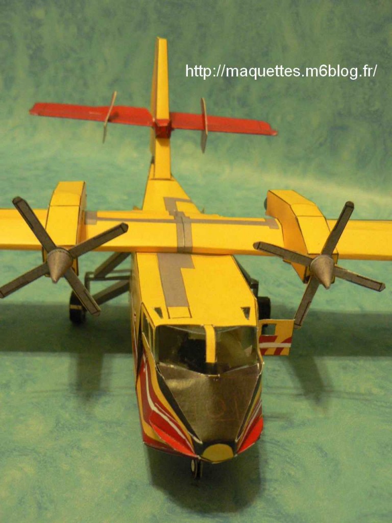
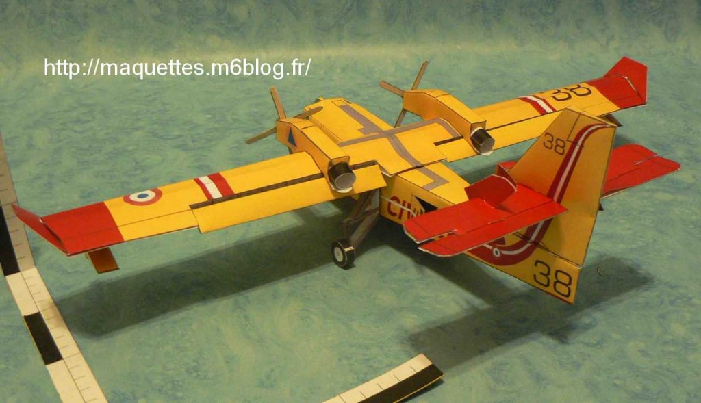
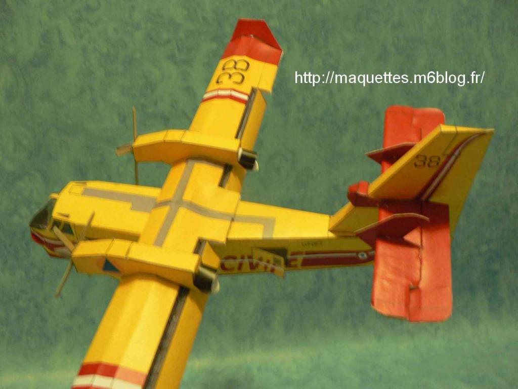
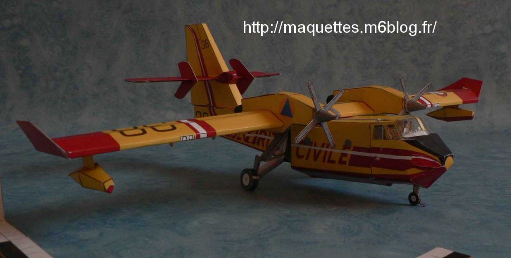
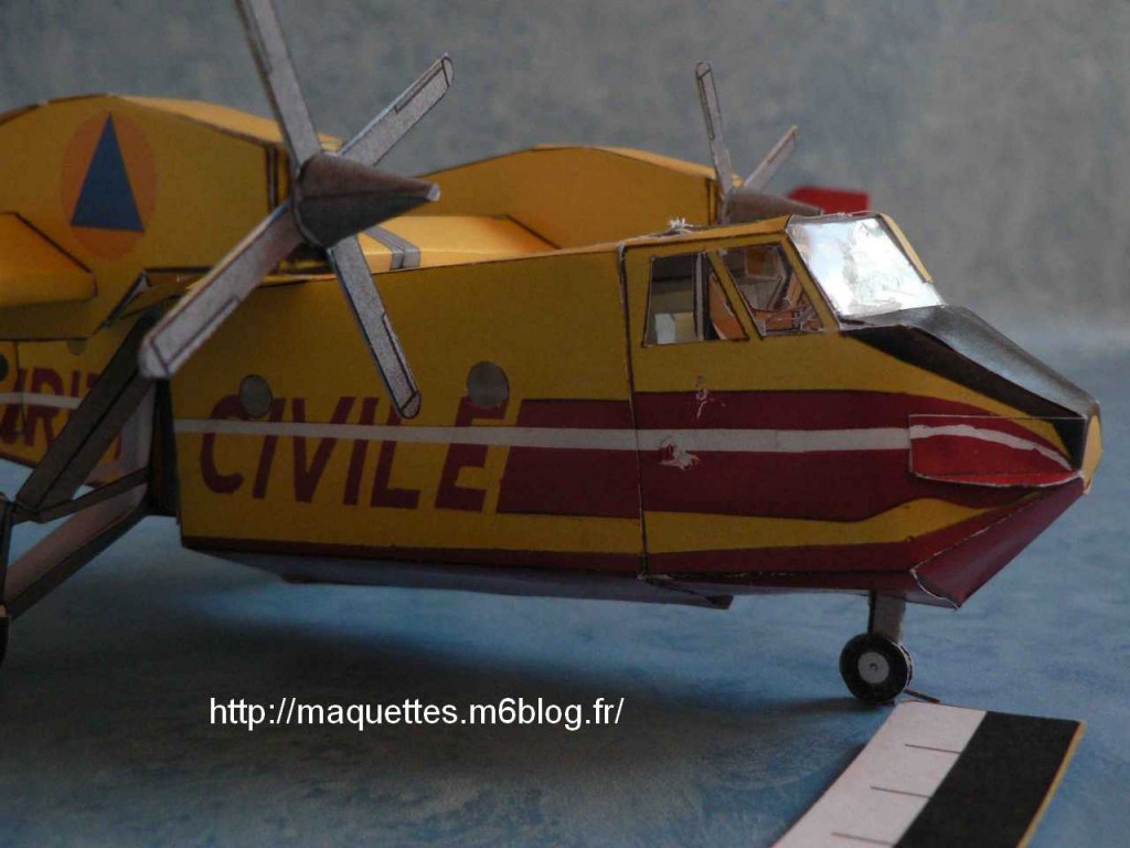
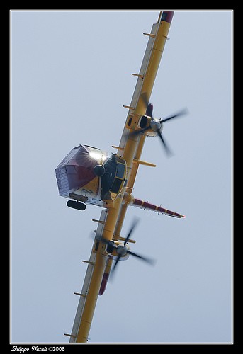
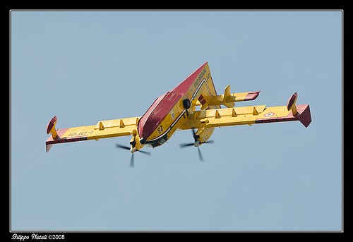
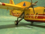
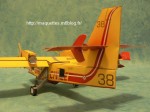
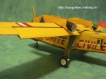
Photos d'une maquette construite en mars 2009 / picture of a model built in march 2009
|
|
|
|
|
|
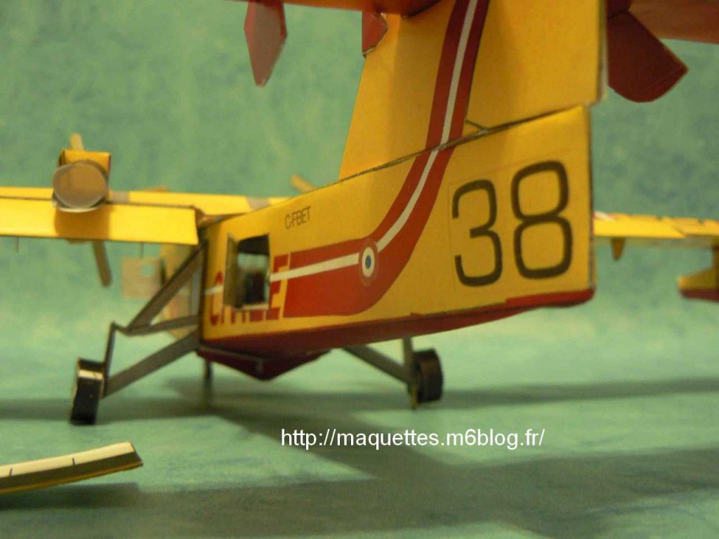
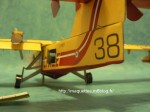
 détail du train d'atterrissage |
|
|
|
|
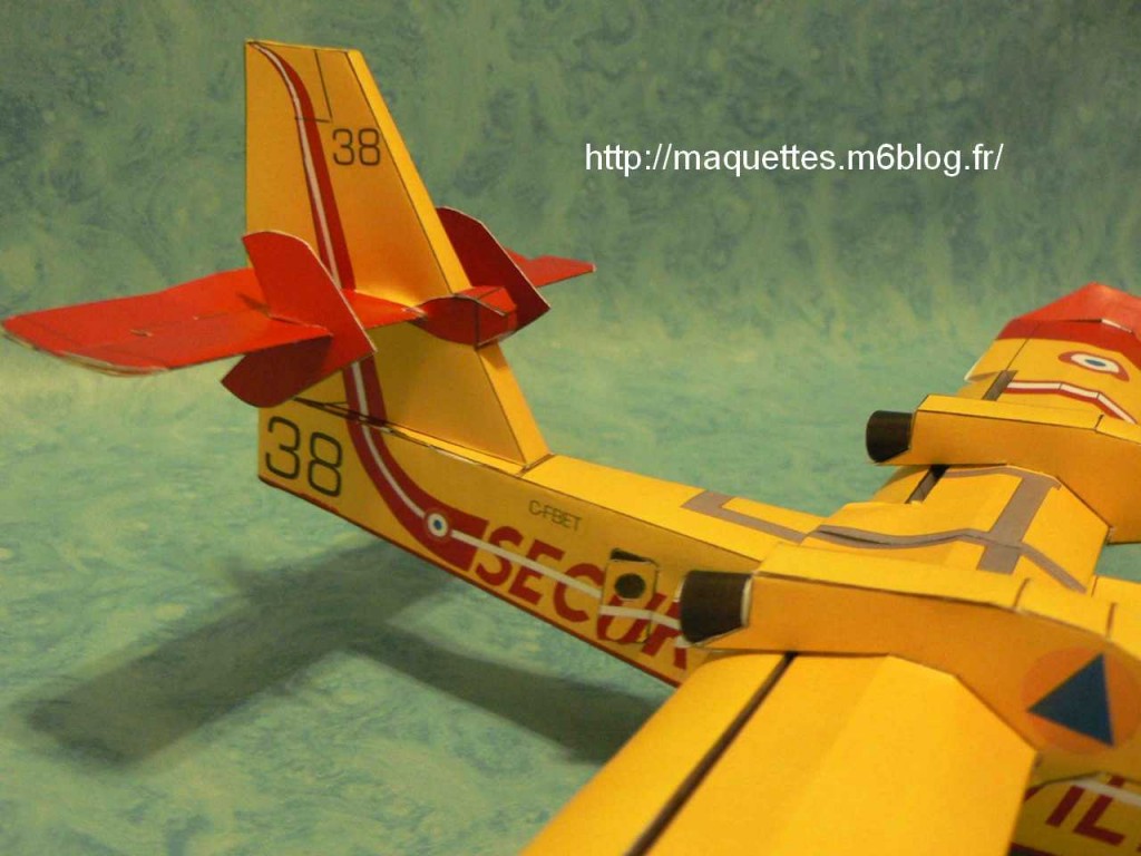
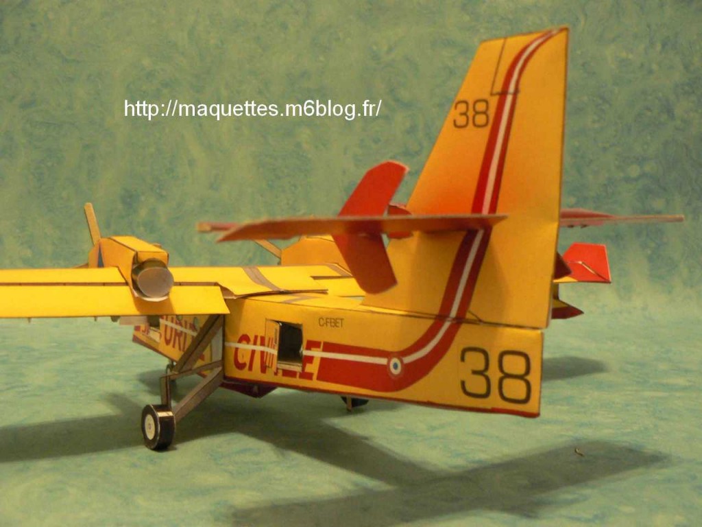
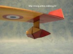
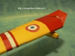 zoom sur la dérive et l'empennage |
|
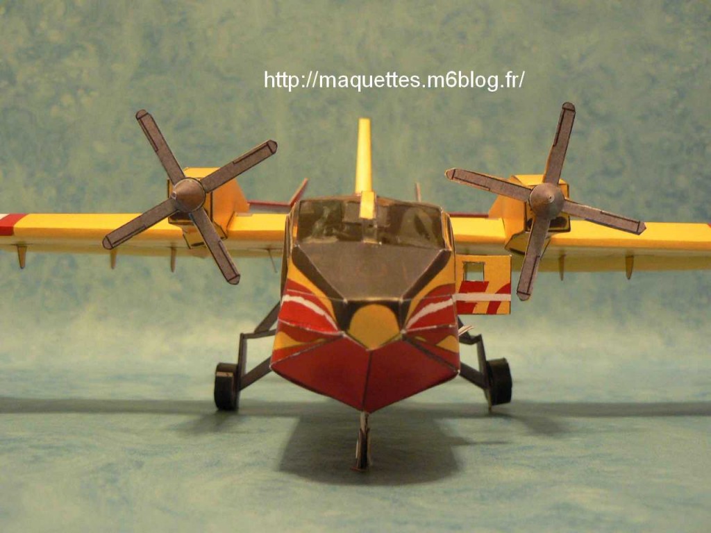
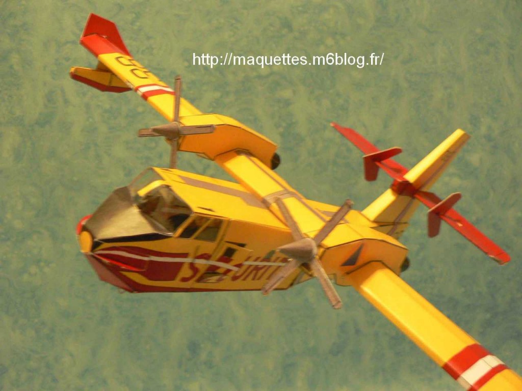
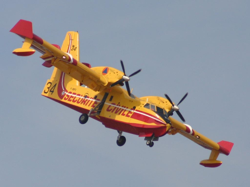
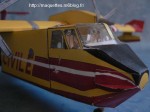
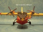 vue de face
|
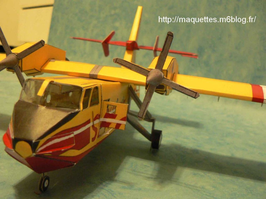
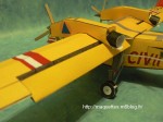
 les nacelles de moteurs et volets rentrés |
 volets légérement sortis
|
|
|
|
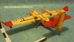
 vue d'arrière |
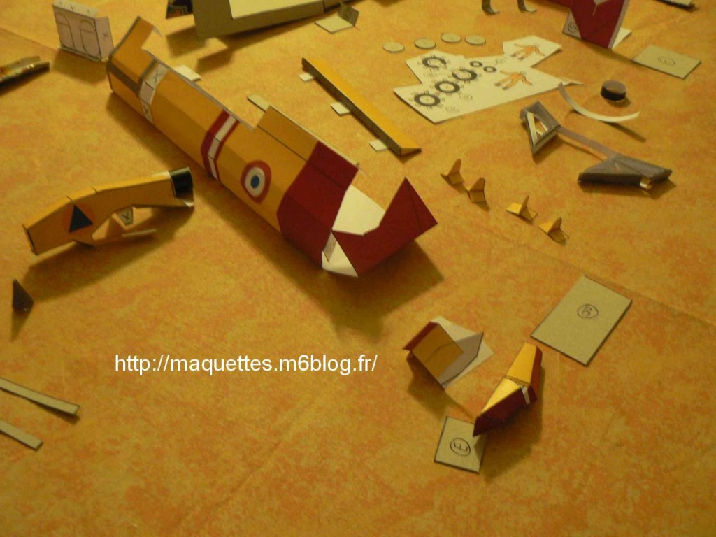
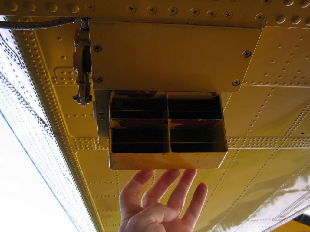
zoom sur le flotteur
|
|
|
|
|
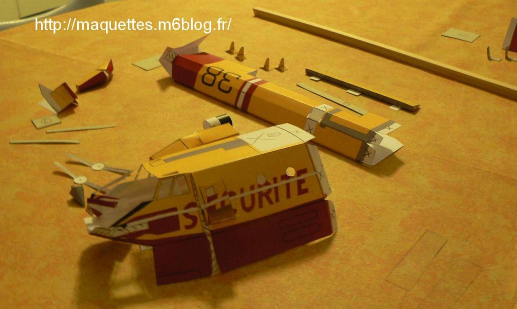
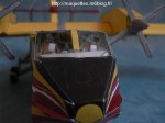
 le cockpit (impossible à coller au montage) et le renfort de nez (oublié pendant le montage) |
 zoom sur le cockpit |
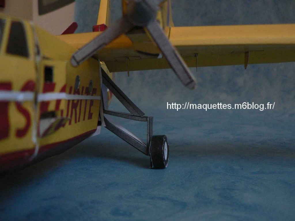
peu de temps après, j'ai réouvert la partie avant pour améliorer le train d'atterrissage avant, j'ai également ajouté un renfort en V sur toute la moitié avant du fuselage !
A few time later, I opened again the front part to improve the front undercarriage, I also added a reinforcement (in "V" shape) in the front part of the fuselage.
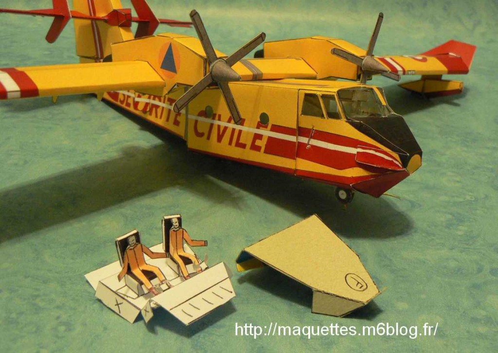
voilà le résulat ! / Here it is !
|
|
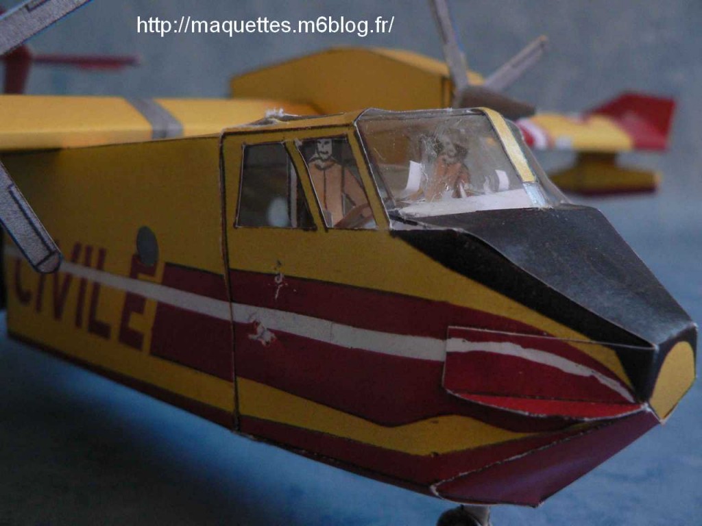
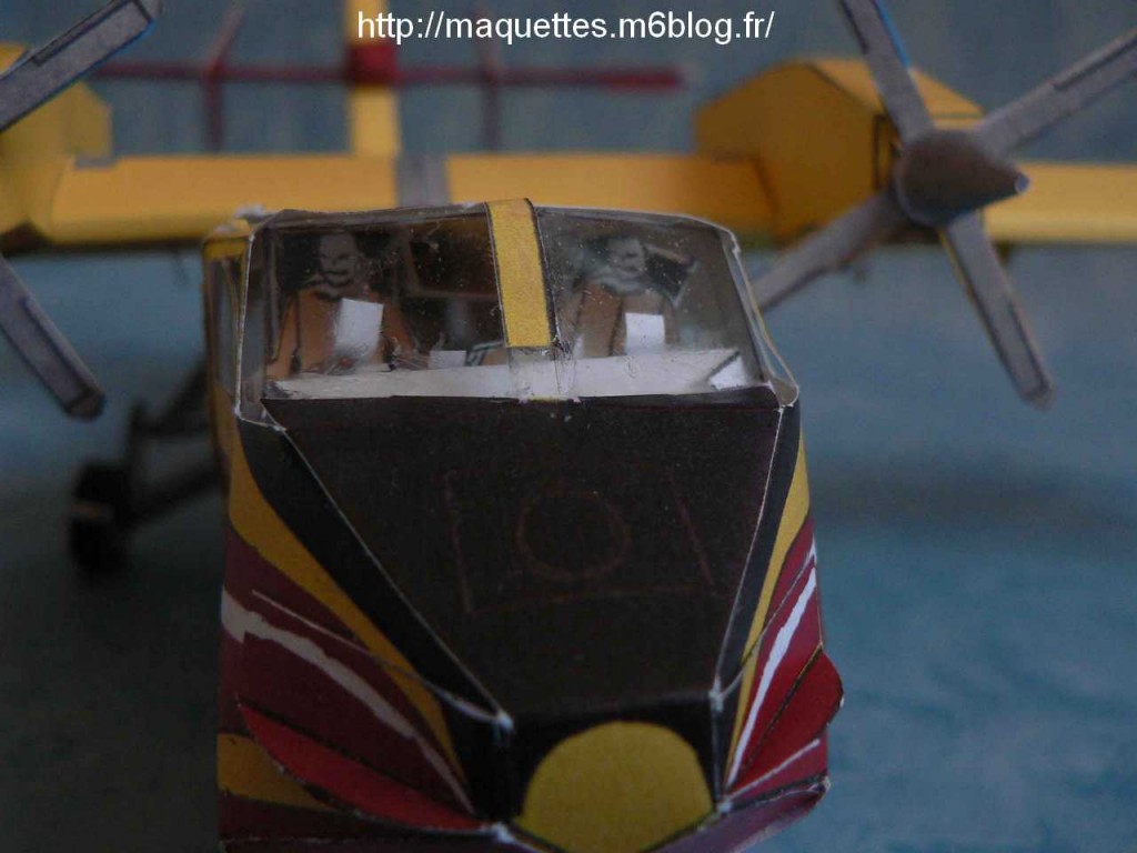
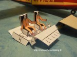
 le cockpit avec les pilotes ! |
 zoom sur le cockpit / zoom on cockpit |
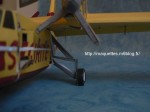 renfort du train d'atterrissage |
|
|
. |
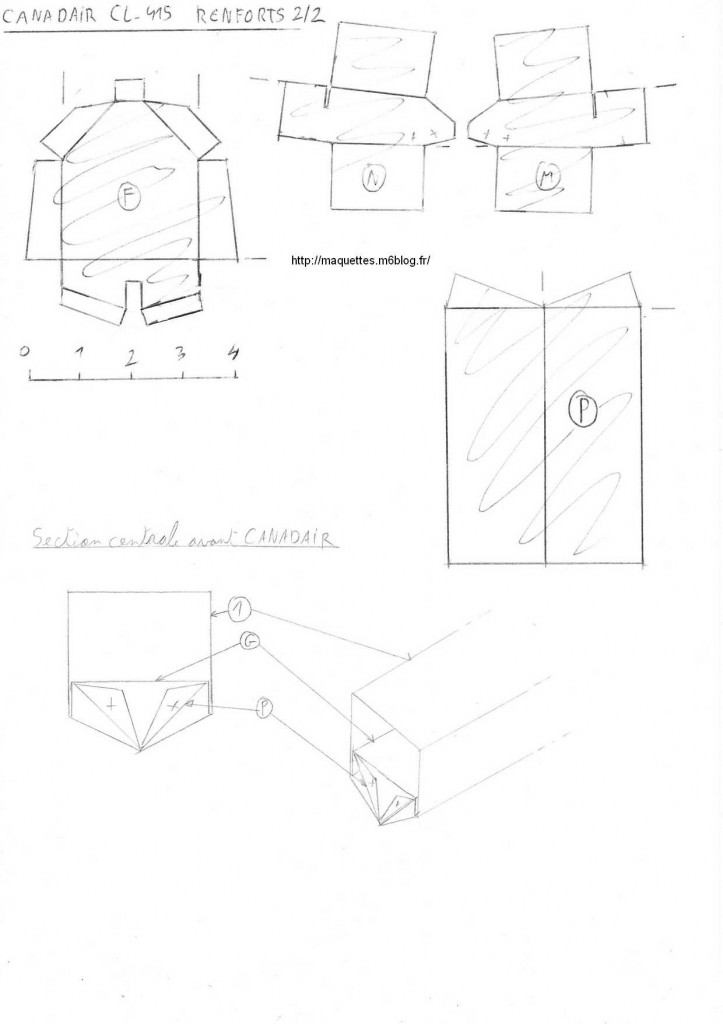
CONSIGNES DE CONSTRUCTION :
- un bois de section 1cm x 1cm et de longueur 42 cm est nécessaire !
- des ouvertures fines sont à réaliser sur le dessus des ailes pour glisser les languettes de fixations des moteurs et à l'arrière de la queue (face supérieure) pour y glisser les languettes à la base de la dérive verticale (cela aidera à l'assembalge).
- Une ouverture est à faire à travers la dérive verticale pour y glisser le refort de l'empennage horizontal !
- les hélices ont été réalisés fixes sur les moteurs ! elles peuvent être posées sur un disque plastique ( à la place de renforts en carton) ou avec un système pivotant de disque !
- les volets à l'arrière des ailes sont orientables !
- le train d'atterrissage avant et arrière est en option ! Les pièces M et N servent d'appui et de pivot à la jambe avant ! Ces pièces s'appuient sur le plancher du cockpit pour ne pas remonter !
- Du poids doit être rajouté dans le nez , pour équilibrer la maquette !
BUILDING INSTRUCTIONS :
- You need a wood stick of 1cm x 1cm ( length 42 cm)
- Fine openings have to be realized on the top of the wings to slide theenfine fastening tab, and also on the tail ( superior face) to slide the taps on the base of the vertical drift base (it will help in the assembly).
- You need to make an opening through the vertical drift to slide the reinforcement of the horizontal tail there.
- Helixes are fixed in the engines. They can be put on a plastic disk (instead of cardboard reinforcements) or with a swivelling disk system.
- You can adjust the shutters on the back of the wings.
- Front and back undercarriages are optional. Parts M and N are used as support and as pivot for the front leg! Those parts lean on the cockpit florr in order not to raise.
- Weight must be added in the nose, to balance the model.